Mechanical rigging, tips and tricks?

Okay guys, i’m new here, let me present myself.

I have been trying to design a car suspension system for a while. Before, i was using solidworks, but i got frustrated by the limitations offered by it in order to design and study the kinematics of the suspension geometry (how everything moves together and the impact of each motion) Basicly, when it comes to motion - while concepting, i felt kind of stuck, having my sketches and constraints breaking all the time.

Eventually, time passed, and being a 3D artist, and having switched to Maya about last year, i started learning how to rig - something that i never did before. After a few character rigs tutorials, came to me the idea to try to design my suspension system in Maya.

What i am trying to create is a “double wishbone” suspension system. Now, there are a few tutorials out there explaining how to rig a car’s suspension, but none of them seem to do it the way i’d like it to be done. Most of them use some parallel “wishbones”, and their rotation is within a plane. What i have in mind is something a bit more complicated than this, beceause my wishbones are absolutely not parallel, and have different rotation axis.

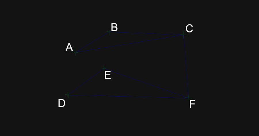
I will try to illustrate a bit better what i have in mind, but overall, i feel stuck on some “concepts” that i can’t seem to grasp. Here is a picture that i hope will illustrate well enough what i’m trying to achieve :

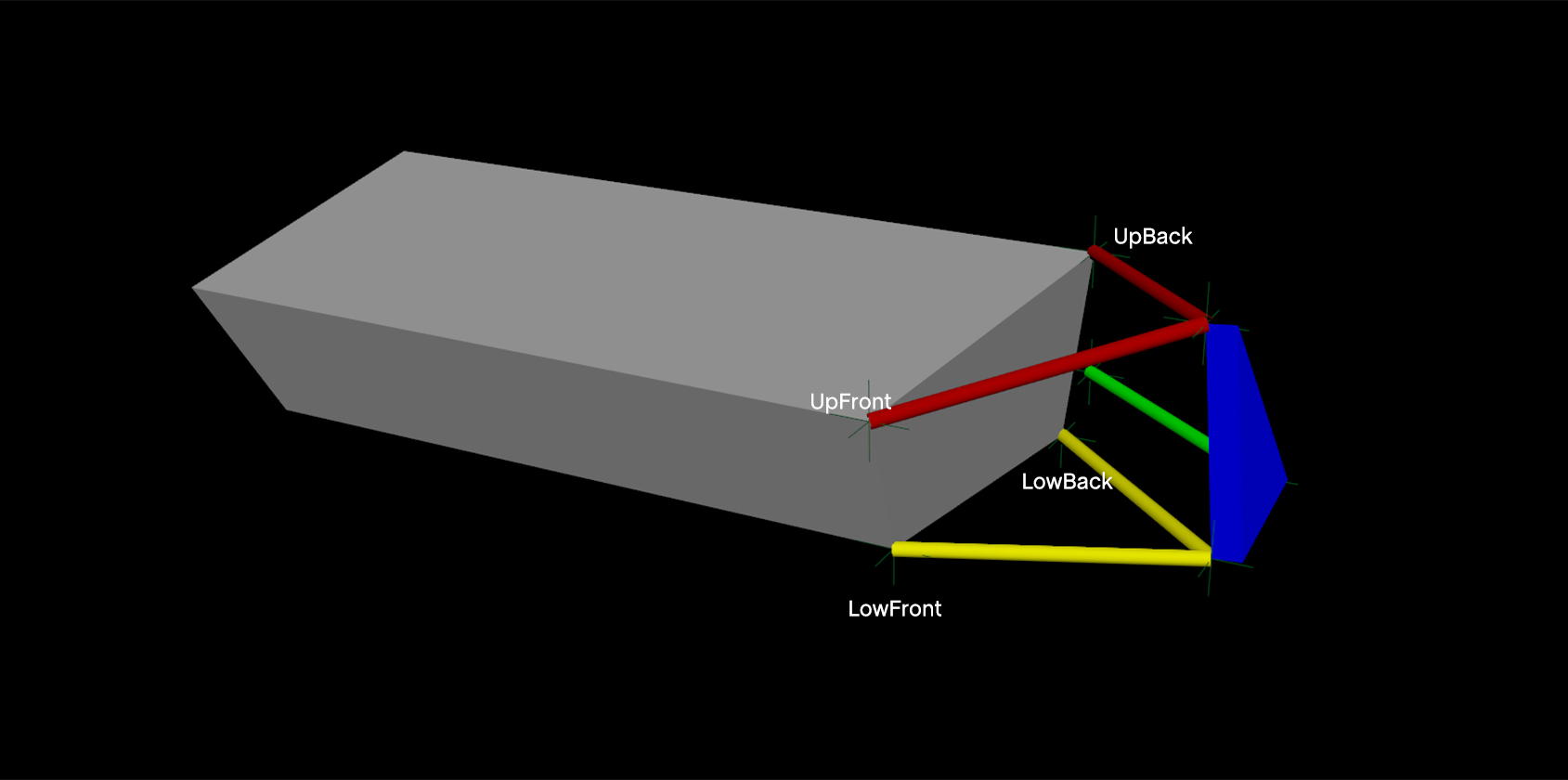
The grey mesh represent the car’s frame on wich are attached the wishbones. In red is the upper wishbone, and yellow is the lower wishbone. Each wishbone is supposed to be totally rigid within itself (a piece of steel).
In blue is the knuckle, wich is attached to the upper and lower wishbones by ball joints.

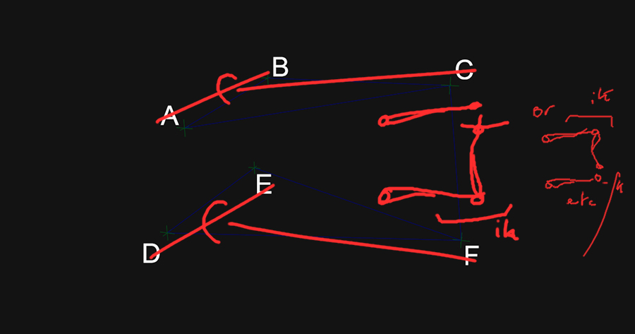
So, each wishbone is supposed to rotate from the axis defined by the two attach points on the chassis. For example, for the upper wishbone, the rotation axis is supposed to be a line between “UpFront” & “UpBack”. Same thing for the lower wishbone (yellow). Up to there, it would have been kind of easy to just have one bone per wishbone and aligning the rotation axis to the desired axis. But the problem is that each tip of the wishbones is supposed to be attached to the knuckle (blue). So, when i rotate one wishbone, the other would need to be driven by the first. The problem is that using an ik seems to screw the rotation axis of the first wishbone, and since the pole vector would need to be dynamic an move relative to it’s own bones rotation, it gets so complicated that i don’t even know what i’m doing anymore.

In the end, this seems like a very specific issue, but i’d like to create this rig quite flexible, to be able to move each attach points (locators in the picture) to be able to analyse the effects of moving them on the overall geometry.

I became quite obsessed with this and would like to find a solution, even if i realise using rigging for suspension geometry is probably not the best option, but i’d like to be able to create mechanisms, as much as complex than simple. But some seemingly easy things looks so complex… If anyone would have time to explain me some things on how to setup stuff like “perpendicular” constraint, or having a locator constrained between two other locators (like point constraint of one locator between two locators but instead of having it in the middle, being able to have it in a position perpendicular to a 4th locator?), & stuff like that.

I know i am vague, but i have to say i’m quite lost haha.

1 Like

Cool, you’re me! :smiley:
I specialise in mechanical stuff, and I’ve experienced a lot of the same frustrations. The most important thing to work out about any rigged system is the behaviour you want out of the end of it - if that behaviour is simple (like here, correct me if I’m wrong but the desire is for the blue output to always remain vertical as it translates up and down?), your life can be much easier.

For your “perpendicular constraint”, the easiest answer is often just an orient constraint. Orient and point constraints affecting only one axis were my bread and butter for a long time, especially when combined with rotating drivers or parent groups - you can produce very sophisticated skewing behaviour with not many nodes. The handy and frustrating thing about mechanical systems is that you don’t need to connect the motion methodically from part to part - if there’s another component that shares the characteristics you need, just use it as a source and fill in the rest.

Sorry if it’s a bit incoherent, but going completely forwards-first through these things is rarely the best or easiest way - treat them more like sudoku.

Hi EdArt !

I am sorry to anser so late, i actually just remembered that i posted here.
I went a bit further into this. The thing is, no, the blue output is not supposed to remain vertical at all, it is supposed to move depending on the rotation of the “Top triangle” and the “Bottom triangle”.

I did a little animation to show you how it is supposed to behave, but i cheated. I rotated the bottom triangle then keyed each frame of the top triangle so it matches the distance from tip to tip.
As you can see, the line of “tip to tip” doesnt remain vertical. It moves depending on the rotation axis of each triangle.

anim_01

I feel like i have tried every option possible with IK and i can’t find a solution.
I feel like there could be a solution to this but i would need a way to calculate a dynamic pole vector for the top triangle tip. So basicly, it would be the same thing as calculating where the tip of the top triangle should be depending on the bottom triangle’s rotation.

(just dropping this here so it’s easier to talk about : )

As a result, i started learning vector maths and i am trying to solve this mathematicly to try to write an expression defining the position of C point depending on where F is… So far, i managed to write a Python script that works to calculate each vector and the distance between each point, but i don’t know yet how to calculate where the C point should be.

If anyone here is good with maths and knows how to do this, i’d be glad. One possible solution would be to do a “trilateration” (that i don’t understand yet how to do mathematicly), and that should give me two possible results for C position, then pick the one that has a highest Y value than F?

Otherwise, the C point should always remain on a circle of a certain radius, wich center would be the closest point of the AB vector to the C point, and that would be perpendicular to AB vector. That would be equivalent on applying a rotation matrix of C around the AB vector. But from there, i have no clue how to calculate which exact point of the circle should it be depending on the DEF rotation on the DE axis.

I guess i’ll need to have a look at how to solve equations that can have multiple possible results and crossing them to find the right solution? but i don’t know how that’s called. If anyone has pointers, i’d appreciate.

When I have to do this kind of stuff, I always use this website: http://geomalgorithms.com/
There’s code on there that can handle most of the vector-style constructions that you need.

If I were to do this, I would:
Project F onto DE (call it G): http://geomalgorithms.com/a02-_lines.html
Construct the plane that F can lie in when it rotates about DE (A plane is just a point and a normal, so point G and normal GD).
Construct a sphere centered at C with radius CF (A sphere is just a point and a radius)

We need the circle of intersection between the plane and sphere defined above, so…
Project C onto this plane (Call it point H): http://geomalgorithms.com/a04-_planes.html
Then use some simple trig to get the radius of the intersection circle HF.

So the next thing we do, is intersect the two circles we have, and then move F to one of the 2 (or fewer) possibilities, but that involves more annoying steps …
So this is where I would use maya, and just do some trig and rotate F around DE by angle FGH, and again by the angle of the triangle formed by lengths GF, HF and GH.

2 Likes

So I might be reading this wrong, but it seems like your two wishbones are just solid A-frames, pivoting from their bases - is there a reason you need to include each of their edges at all? Don’t know if this helps:

So if you can just treat it as three segments, the problem becomes trivial, either with maths or with maya - assuming that we know the position of one peak, from FK or matching the position of the wheel, then as Theodox said we just intersect two circles - one centred at the unknown wishbone’s pivot, and one at the known.

It’s worth noting though that simple geometric operations like this almost always have two valid answers (two circles cross at two points, unless they’re tangent), so the only way to avoid flipping is to apply some condition to the results, or to introduce hysteresis and store the value from the previous computation. It can be done, but an ik handle will be faster and more stable.

Hi !

Thank’s for the ressource tfox, reading trough it and trying to understand (didn’t do maths since i was 16, so this might take a while to tilt).

EdArt, yes, you’re right, it will have two valid answers and i will need a way to find wich one is good, that’s what i was talking about when i mentionned getting the one with a highest Y value than F.
On an other note, keep in mind AB and DE are not parallel. Yes the wishbones are solid A frames, but they each rotate around a different axis. There is no “need” to include each of their edges, but if i don’t, ik simply won’t rotate based on that axis?

rigexample
(it’s a video converted to gif, i hope it plays correctly)

Here, i exagerated the angles so it’s more obvious. What i did here is an example of how close i managed to get this with IK, and pretty close to the way you show in your drawing, except i just used a “triangle” ik setup with pole vector for the bottom part and i’m just moving the pole vector while the Ik handle of the top part is point constrained to the tip of the bottom triangle joint. I understand it would be faster and more stable, but I did not find a solution to solve the problem of having one of the wishbones rotating on an other axis than it’s base. Maybe there are tricks with pole vector that i’m unaware of to force it to rotate as on a plane perpendicular to AB vector and passing trough C? Beceause that would solve everything.

Knew I was missing something - yeah, that’s a rough one. As far as I know there is no way to coerce this out of pole vectors and Ik handles. I’ve done something similar here: https://vimeo.com/245584889 (please don’t judge the rest of the reel lol). For the carpal joint “elbows” I had to basically find the intersection of the two axes of rotation; as there was no intermediate link, I just projected one on to the other, but here it’s necessary to do something like what Theodox said.

However, depending on which wishbone is your driver, all you need from one triangle is the peak for any position. Say the lower is our driver as in the gif - if we know F, we intersect a sphere at F of radius CF with a plane of normal AB to find a circular domain, then intersect that with a sphere at AB/2.
There might be more I’m missing, but let me know how it goes