Z up to Yup using Maya API MMatrix C++

So I’m writing an importer for our engine skeleton data into Maya (to learn C++ and the Maya API)
the skeleton data is stored as Rotation(xyzw Quaternion), Scale(x,y,z vector) and Translation(x,y,z vector)

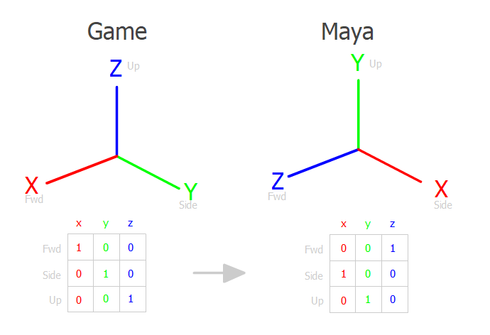
I am confronted by the ubiquitous Z-up vs Y-up conversion.

I solved this ‘brute force’ swapping the xyz components:

/*================================
engine Z up  to Maya Y up 4x4 matrix
  x y z w
| 0 0 1 0 |
| 1 0 0 0 |
| 0 1 0 0 |
| 0 0 0 1 |
==================================*/


// 'brute force' axis swapping based on the matrix seems to work
void engineToMayaSpaceVector(MVector & v) {
	MVector temp;
	temp.x = v.y;
	temp.y = v.z;
	temp.z = v.x;
	v = temp;
}

void engineToMayaSpaceQuat(MQuaternion & q) {

	MQuaternion temp;
	temp.x = q.y;
	temp.y = q.z;
	temp.z = q.x;
	temp.w= q.w;
	q= temp;
}

The above code seems to do the trick.
But I believe (correct me if I’m wrong) that this can all be done by a matrix multiplication?

mayaScaleVector = ZtoYupMatrix * engineScaleVector
mayaRotationQuaternion = ZtoYupMatrix * engineRotationQuaternion
mayaTranslateVector = ZtoYupMatrix * engineTranslateVector

When I attempt this I get very incorrect results.
Is my premise wrong, or is my execution flawed?

/*================================
for MMatrix, we need to build a float matrix[4][4]
where the x,y,z,w components are each row (i think)

   x y z w
i| 0 0 1 0 |
j| 1 0 0 0 |
k| 0 1 0 0 |
l| 0 0 0 1 |

const float matrix[4][4] ={ 
	xi,xj,xk,xl,
	yi,yj,yk,yl,
	zi,zk,zj,zl,
	wi,wj,wk,wl
} 
   ^^^^^^^^^
   (is this the correct way to build the matrix?)

==================================*/

const float ENGINE_TO_MAYA_ARRAY[4][4] = {
	0.0, 1.0, 0.0, 0.0,
	0.0, 0.0, 1.0, 0.0,
	1.0, 0.0, 0.0, 0.0,
	0.0, 0.0, 0.0, 1.0
};

const MMatrix ENGINE_TO_MAYA_MATRIX = ENGINE_TO_MAYA_ARRAY;

//convert by matrix multiply
void engineToMayaSpaceVectorMatrix(MVector & v) {
	v = ID_TO_MAYA_MATRIX*v;
}

//convert by matrix multiply
void engineToMayaSpaceQuatMatrix(MQuaternion & q) {
	q = ID_TO_MAYA_MATRIX*q;
}

It looks like what you’re doing is a 120deg rotation around the (1,1,1) vector, which I don’t think I’ve ever seen used as a translation from Z-up to Y-up. I don’t see anything wrong with it, it’s just not what I expect. I deal with 3dsMax to Maya and back, where everything is just a 90 degree rotation around the X axis.

So only because I haven’t seen this before, I have to ask if this is how you are supposed to be doing it? The way to know for sure is to export a mesh from Maya to your engine and see if the X axis is pointing in the same direction relative to the mesh in both cases.

Or if you’re going to be the one creating that exporter, take care and make sure that if I imported something from the engine into Maya, exported that to another software, and then exported from that software to the engine, then I would get what I expect in the engine.


Yes, the translation between Z-up and Y-up can be handled by a matrix multiplication.
That said, down in your matrix mult section you’re handling vectors and quaternions separately, and I wouldn’t do that here. There’s definitely a time and place for keeping them separate, but it’s just so much easier for this lower level stuff to combine everything into one matrix.

Or if you’re feeling really fancy, you could create a new class that keeps tran/rot/scale separate, but allows you to multiply with it like a matrix. I wrote something like that at work for python scripting in our rig builder.


The rotation of 120deg around (1,1,1) is the same as the quaternion (0.5, 0.5, 0.5, 0.5). I took a random unit quaternion and multiplied it by that (0.5, 0.5, 0.5, 0.5), and the output wasn’t the same as your brute force manipulation. It wasn’t even a rearrangement of the same numbers, all the numbers in my output were completely different from the input.

I don’t have a real intuition with quaternion components, so I could easily be wrong here, but I would definitely double-check that your brute force method is doing what you expect.


Another thing that may be biting you is you may be applying the ZtoY matrix in the wrong places.
One very simple way to handle this is to just put everything under a parent object, and rotate that.

However, when I had to deal with this, our modelers didn’t want rotation values on their meshes, but I still had to handle skeleton hierarchies, and I couldn’t add extra objects. So here are some rules I found so that hierarchies work as I expect, but meshes come in oriented to the current world up.

These rules are not the end-all, they’re just what’s worked best for me in my studio.

  1. If the current object is a mesh, apply the ZtoY matrix to the vertices, and multiply the inverse of the ZtoY matrix with the object transform.
  2. If the current object is at the root of the scene, multiply the ZtoY matrix to its transform. This happens whether or not step 1 happened.
  3. If the current object is a child of a non-root mesh, compensate for the mesh’s ZtoY rotation in its parent space.

So if there’s a mesh at the root of the scene, you move all the verts, and counter-rotate (step 1). Then you apply the ZtoY matrix because it’s at the root (step 2). The counter_rotation * rotation cancels out and means that meshes at the root of the scene come in standing up without any rotation values, but any other meshes stay oriented to however the artist set up the scene.

That also means that you don’t mess with skeleton hierarchies. Riggers don’t care what the up vector is for the scene (or, at least mine don’t :slight_smile: ), they care more for what the first, second, and third Euler axes are, and will set up their joints with that in mind to avoid gimbal lock.

In this section, I talk about a ZtoY matrix, but you can use whatever rotation matrix you need (be it 120 around (1,1,1), or 90 around (1, 0, 0), or whatever else) because it’s just multiplied into the hierarchy.

Another thing is that step 3 above can be generalized to work with any ruleset. It’s kind of complicated to explain. If you want to know, just ask

1 Like

Thanks for taking the time to scrutinize my work, I appreciate it.
I’m not applying this to meshes (not yet anyhow), skeleton joints are my test case.


With the ‘brute force’ component swapping, the game joint data are definitely importing to the same positions and rotations as their Maya source joints (well, the source rotations are actually stored in joint orient values)


The image below shows the logic I followed building my matrix, based on a thread from gamedev.net I believe, asking What basis do I need to multiply each XYZ component by to orient it correctly in the new coordinate system?

engine_to_maya

This gives me a 3x3 column vector matrix, and I am not sure I correctly converted it to a 4X4 MMatrix.
In the API docs MMatrix is just an abstract [4][4] array with no defined ‘roles’ for columns or rows or cells.


If I want to combine SRT vectors/quats into a single MMatrix, what is the process for that?
I have read that an open GL 4x4 matrix is organized by column vectors thusly:

R R R T
R R R T
R R R T
0 0 0 1

Is a MMatrix representing a transform similarly arranged?
Do I take MQuatertion.asMatrix(), and set the 4th column to the S*T vector?

Scale and rotation are linked, while translation kind of does its own thing. So to directly build a matrix, you’d build a scale matrix, and multiply it by a rotation matrix, and set that to the upper/left 3x3. Then the translation is just the first 3 entries in the bottom row.

Instead of doing that, though, it may be easier to use an MTransformationMatrix instead of an MMatrix. It’s got a lot of convenience methods for building the matrices you use directly from S/R/T components.

Another issue is that Maya interprets its matrices as the transpose of the OpenGL ones (ie. DirectX style). This may also come to bite you because transposing matrices also reverses their multiplication order. A * B == (B.T * A.T).T

The documentation of MTransformationMatrix also shows how the matrices in maya are built and multiplied together.

1 Like

While your space conversion matrix looks right (for going from Z-up right handed to Y-up right handed), I think your maths in this area isn’t correct.

For converting a vector you can post-multiply by the space matrix, that part is fine.
For a matrix, you have to pre-multiply by the space matrix and post-multiply by the inverse space matrix.
(remember, matrix multiplication is not commutative)

If you are importing scale, rotation and translation data… unless you have an explicit need to keep them separate I would say it’s easiest just to build that into a MMatrix and then apply your space conversion matrix.
Finally just setting the joint matrix directly (accountinf for whether your format uses parent relative bone transforms or not).

eg in Python

ZtoYupMatrix = MMatrix((
    (0, 0, 1, 0),
    (1, 0, 0, 0),
    (0, 1, 0, 0),
    (0, 0, 0, 1)
))
engineMatrix = engineScaleVector * engineRotationQuaternion * engineTranslateVector
mayaMatrix = ZtoYupMatrix * engineMatrix * ZtoYupMatrix.inverse()
1 Like

Thanks again for you considered advice. I think I will try building an MTransformationMatrix for each joint and multiplying by my zup to yup matrix.

@ross-g your example MMatrix actually seems to swap rows & columns vs the MMatrix I built in my example. My X vector for example is row 0 where yours is column 0. Is your method correct , then?
This is a source of confusion for me, as I haven’t found explicit documentation explaining what the columns or rows of MMatrix are supposed to represent as far as XYZ vectors.

Is this the correct way to construct a MTransformationMatrix from an MQuat and 2 MVectors?

MTransformationMatrix gameTransform(MQuaternion r, MVector s, MVector t) {

	//convert s to a double[3] because you can't .setScale() with type MVector 
	double scale[3];
	s.get(scale);

	//convert t to a double[3] , same reason
	double translate[3];
	t.get(translate);

	MTransformationMatrix m;
	m.setScale(scale, MSpace::kTransform);
	m.rotateTo(r);
	m.setTranslation(translate, MSpace::kTransform);

}

@Mambo4 As far as the Python API 2.0 goes … yes that is correct, as @tfox_TD mentioned the matrices in Maya are DirectX style (row major order) ie

R R R 0
R R R 0
R R R 0
T T T 1

And going by the Python docs you should construct an MMatrix from either 16 floats, or 4 tuples of 4 floats each. With the values being interpreted in row order either way.


ie
MMatrix((
    (R, R, R, 0),
    (R, R, R, 0),
    (R, R, R, 0),
    (T, T, T, 1),
))

The MTransformationMatrix documentation shows you exactly where every number goes, and how all the matrices are multiplied together to get the final output:

A transformation matrix is composed of the following components:

Scale pivot point point around which scales are performed [Sp]
Scale scaling about x, y, z axes [S]
Shear shearing in xy, xz, yx [Sh]
Scale pivot translation translation introduced to preserve existing scale transformations when moving
pivot. This is used to prevent the object from moving when the objects pivot point is not at the origin
and a non-unit scale is applied to the object [St].
Rotate pivot point point about which rotations are performed [Rp]
Rotation orientation rotation to orient local rotation space [Ro]
Rotation rotation [R]
Rotate pivot translation translation introduced to preserve exisitng rotate transformations when moving pivot.
This is used to prevent the object from moving when the objects pivot point is not at the origin and the pivot is moved. [Rt]
Translate translation in x, y, z axes [T]
Note that the default RotationOrder is kXYZ.

The matrices are post-multiplied in Maya. For example, to transform a point P from object-space to world-space (P') you would need to post-multiply by the worldMatrix.
(P' = P x WM)

The transformation matrix is then constructed as follows:

[Sp]^-1 x[S]x[Sh]x[Sp]x[St]x[Rp]^-1 x[Ro]x[R]x[Rp]x[Rt]x[T]
where 'x' denotes matrix multiplication and '^-1' denotes matrix inversion

Sp = |  1    0    0    0 |     St = |  1    0    0    0 |
     |  0    1    0    0 |          |  0    1    0    0 |
     |  0    0    1    0 |          |  0    0    1    0 |
     | spx  spy  spz   1 |          | sptx spty sptz  1 |

S  = |  sx   0    0    0 |     Sh = |  1    0    0    0 |
     |  0    sy   0    0 |          | shxy  1    0    0 |
     |  0    0    sz   0 |          | shxz shyz  1    0 |
     |  0    0    0    1 |          |  0    0    0    1 |

Rp = |  1    0    0    0 |     Rt = |  1    0    0    0 |
     |  0    1    0    0 |          |  0    1    0    0 |
     |  0    0    1    0 |          |  0    0    1    0 |
     | rpx  rpy  rpz   1 |          | rptx rpty rptz  1 |

Ro = AX * AY * AZ

AX = |  1    0    0    0 |     AY = |  cy   0   -sy   0 |
     |  0    cx   sx   0 |          |  0    1    0    0 |
     |  0   -sx   cx   0 |          |  sy   0    cy   0 |
     |  0    0    0    1 |          |  0    0    0    1 |

AZ = |  cz   sz   0    0 |     sx = sin(rax), cx = cos(rax)
     | -sz   cz   0    0 |     sy = sin(ray), cx = cos(ray)
     |  0    0    1    0 |     sz = sin(raz), cz = cos(raz)
     |  0    0    0    1 |

R  = RX * RY * RZ  (Note: order is determined by rotateOrder)

RX = |  1    0    0    0 |     RY = |  cy   0   -sy   0 |
     |  0    cx   sx   0 |          |  0    1    0    0 |
     |  0   -sx   cx   0 |          |  sy   0    cy   0 |
     |  0    0    0    1 |          |  0    0    0    1 |

RZ = |  cz   sz   0    0 |     sx = sin(rx), cx = cos(rx)
     | -sz   cz   0    0 |     sy = sin(ry), cx = cos(ry)
     |  0    0    1    0 |     sz = sin(rz), cz = cos(rz)
     |  0    0    0    1 |

T  = |  1    0    0    0 |
     |  0    1    0    0 |
     |  0    0    1    0 |
     |  tx   ty   tz   1 |
1 Like

The other thing to remember is handedness – there are row-major and column-major matrices but each can be ‘left-handed’ or ‘right handed’

Y-up to Z-up and vice-versa can be achieved with just a rotation. But between different handedness matrices there will always be at least one negative scale. Handedness flips typically also go with triangle windings, so without extra work you’ll get inverted normals.

See Y-Up to Z-Up (maya to in-game) via Custom Exporter (pymel)

1 Like

Thanks again to all for your feedback. I now am successfully converting the data into Y up Maya space via a transform multiplication.

@Theodox I scrutinized out engine to make sure the handedness wasn’t flipping. I remember that frustrating me in a Max (Z up RH ) to Unity (Y up LH) pipeline a few years back.

One question:
I seemed to be spending a lot of cycles converting between double[3] and MVector for scale values. In my joint struct, I store both translate and scale as type MVector, but I have noticed that in the API, scale values are consistently of type double[3] . Is this is because there is no need for various Vector operations on isolated scale values?

I’m not 100% sure about the implementation details – but in the final version of the the transform the 3 axes of scale (and shear as well) get baked into the length of the X, Y and Z principal axis vectors. So you would want to keep them as doubles to avoid loss of precisions in rotations because they get multiplied together. I assume (w/o checkling!) that the API wants this so that scale operations are consistent throughout