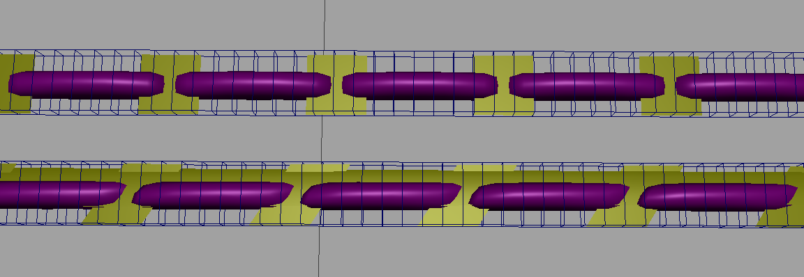
If you have 5 points with a matching normal, and after that another 5 with a matching ( because they are on the same face )
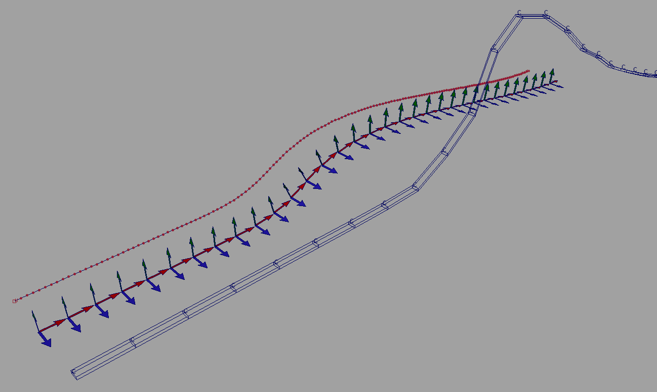
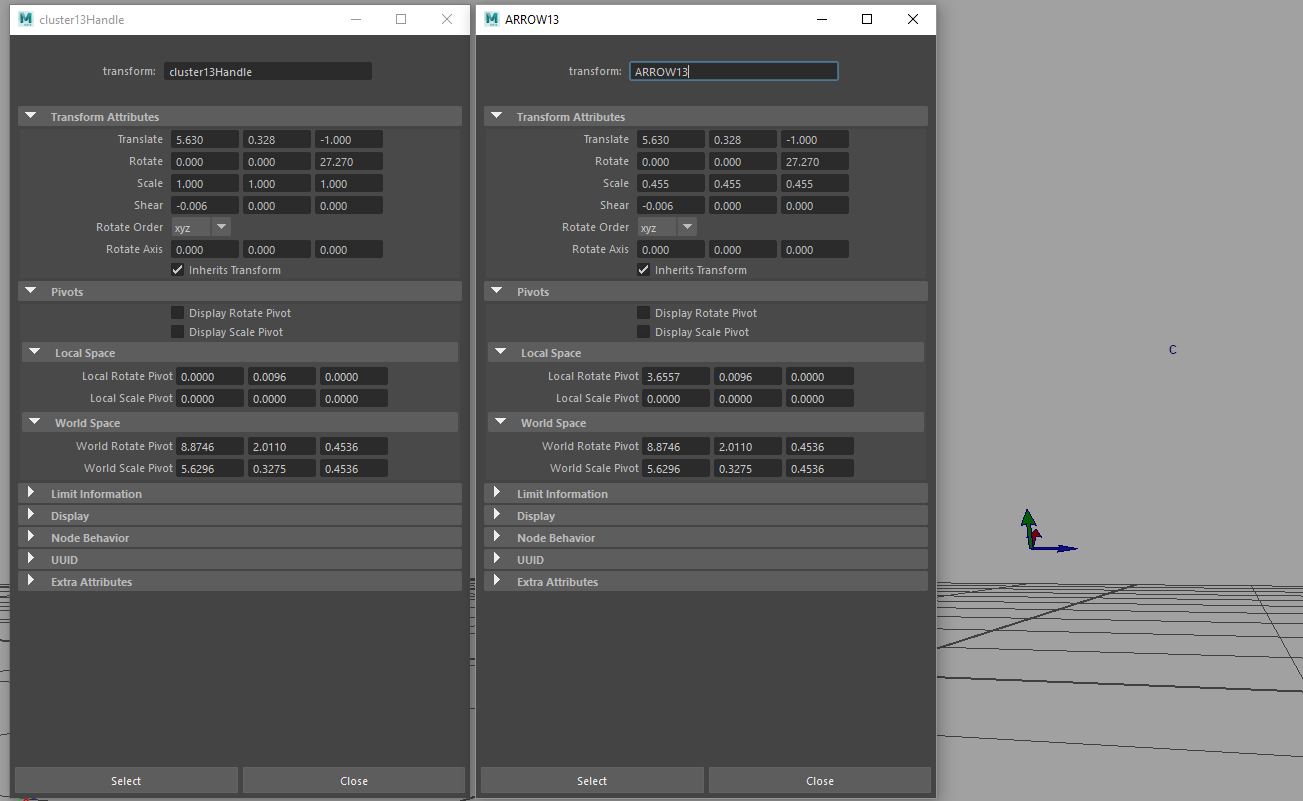
This part is already confusing… I am not dealing with geometry directly. I am using a NURBS curve (converted edge loop) to generate a list of positions in space with tangents. Then for each position in space, I get vertex normal from geometry, so I have 3 vectors: position, tangent, normal. With those vectors, I modify the transformation matrix of a cluster.
E.g I have a 3 lists of 3 vectors (normals, tangents and positions):
N = [(x1, y1, z1), (x2, y2, z2) … (x#, y#, z#)]
T = [(x1, y1, z1), (x2, y2, z2) … (x#, y#, z#)]
P = [(x1, y1, z1), (x2, y2, z2) … (x#, y#, z#)]
Normals are irregular. In such a case is it possible to blend them?